

Arduino Workshop - Parallel LCD Project 1: DFRobot Parallel LCD
Hardware Required:
|
Schematic: No schematic necessary. All connections are made by installing the LCD Shield directly onto the Arduino's sockets. 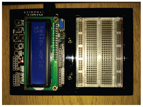 Note: The boards tested use different signal and data pins than the default examples in the LCD Library. Our LCD Shield uses pin 8 for Register Select, Pin 9 for Enable, and pins 4, 5, 6, 7 for data - connecting to Arduino pins 12, 11, 5, 4 , 3 and 2, respectively. You cannot change these pin connections, but must make sure your Sketch code specifies the actual pins being used: // the syntax to specify the connections used by the LCD Shield should read: LiquidCrystal lcd(8, 9, 4, 5, 6, 7); |
Project Steps:
Things to try: (Arduino Sketch examples)
|

Technical Support Community
Free technical support is available for your desktops, laptops, printers, software usage and more, via our new community forum, where our tech support staff, or the Micro Center Community will be happy to answer your questions online.
Forums
Ask questions and get answers from our technical support team or our community.
PC Builds
Help in Choosing Parts
Troubleshooting